dash camera teardown

created  2020/07/04
category hardware
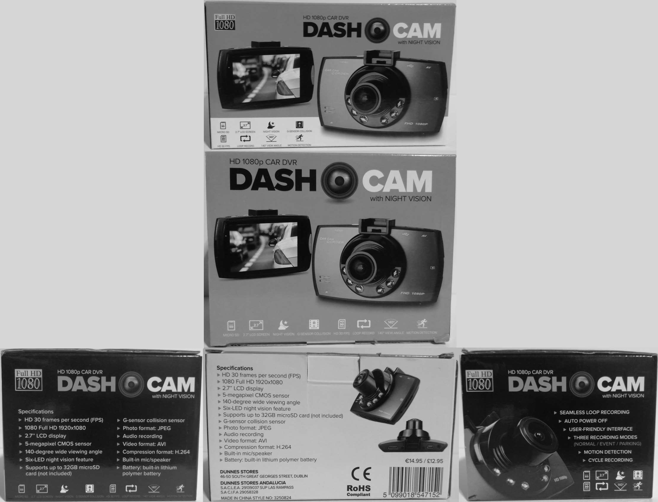
my dad bought this dash cam a couple of years ago, it claims many things of which many are untrue, but to be fair - it's pretty neat it works to the extent it does however considering the 14.95€ price point. i am not able to find any information about it via. the part numbers - although my search wasn't so thorough i am puzzled by my lack of findings. i will be loosely documenting this product and it's internals for the sake of archiving.
accessories
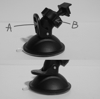
inside the packaging, there is a suction-cup stand for the unit and only one usb mini cable. (which i presume is charging only, but am too lazy to test) the stand has a lever, (A) which when switched to the downward position, pulls the bottom of the suction cup upwards creating suction which holds the unit firmly in place.
the stand also has a 'thumbscrew' (B) that adjusts the sensitivity of the head of the stand - at no point does the thumb screw completely stop the head from moving when tightened or completely loosen it when loosed. (the camera unit is so light that even when the head is perpendicular to the stand it remains stationary)
overview
talking about the unit itself; it has an incredibly short battery life, which i doubt is longer then 15 minutes if not 5, requiring it to be plugged in during use.
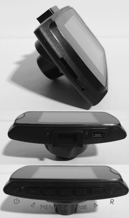
this camera can be operated in two modes; recording (the default mode, press ok to cancel when turning the unit on, or to start recording) and photo. (press ok to take a photo) the images and videos stored on the inserted sd card have proper creation dates but do not contain any metadata other than that.
you can access the settings menu by pressing the menu button, in the settings this camera has three quality modes; VGA, 720, and 1080. VGA records in 640x480, 720 in 1280x720, and 1080 is identical to VGA. you can also set the date and some other unimportant options.
physical discrepancies
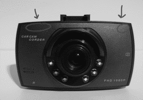
starting with the most noticeable, the screen has a 4:3 aspect ratio as opposed to the 16:9 on the packaging (the screen is also nowhere near the quality or resolution it appears as on the packaging) - and there is no AV or HDMI ports nor markings present on the device. the camera lens does not 'bubble' out of the case as it does on the packaging.
conclusion
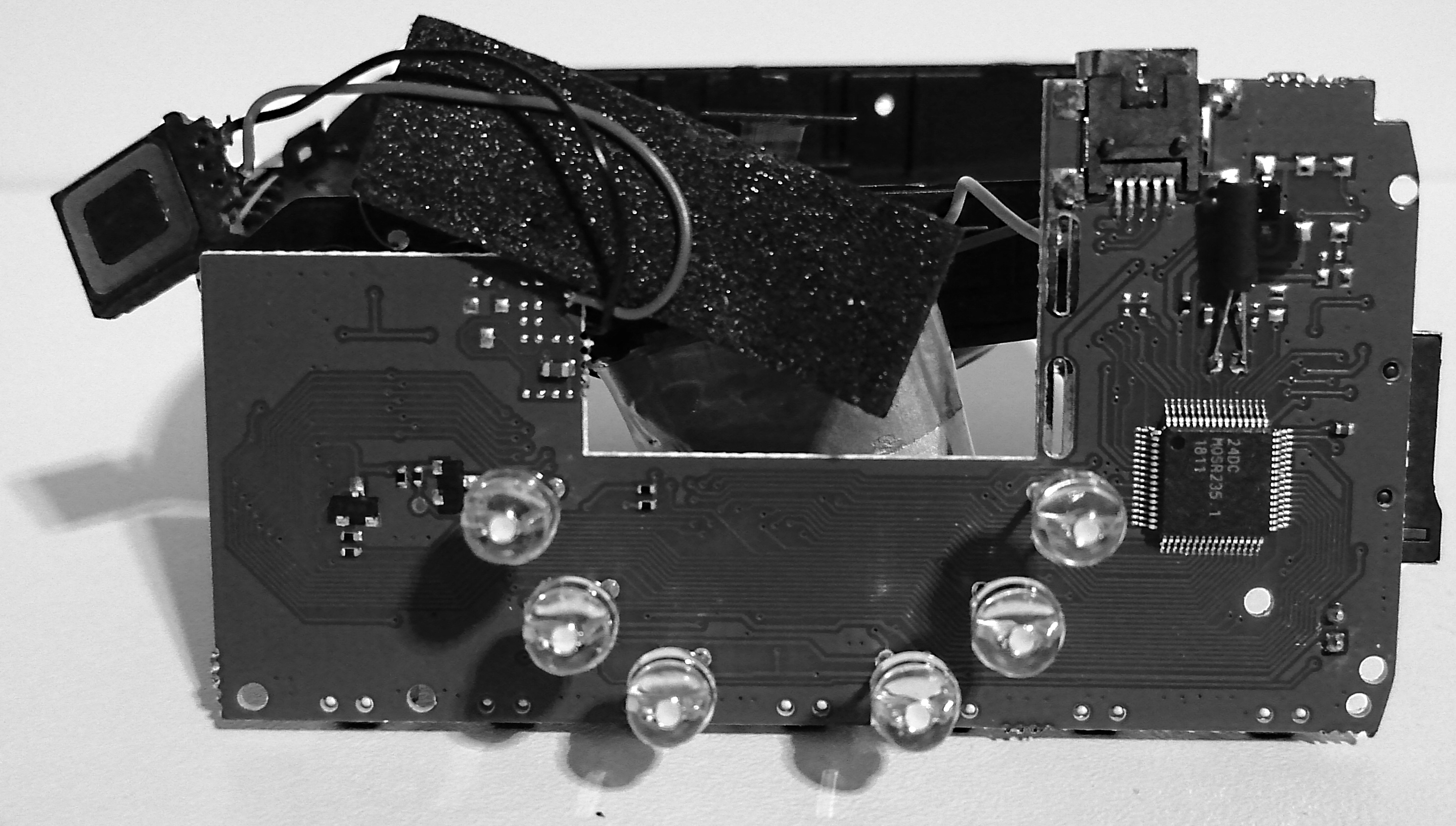
i doubt there is any way to reprogram the onboard microcontroller, of which i could not find a datasheet, (24DC, MO(Q?)SR235 . 1, 1811) so the unit cannot be repurposed in that way
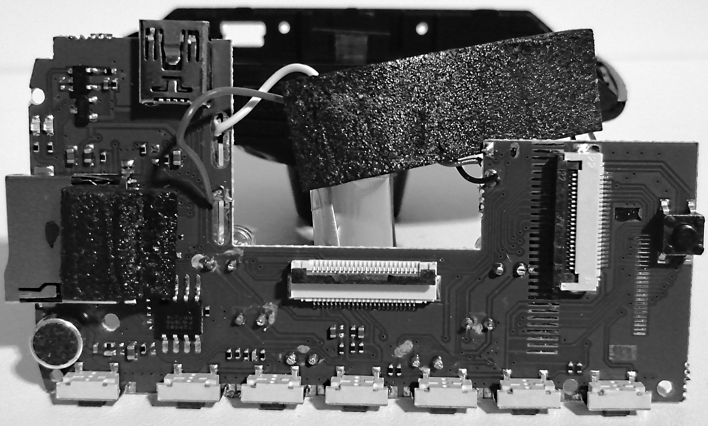
after disassembling, i can only see a few components that could be worth salvaging; the camera, display, (i could not find datasheets for either of those, however) the leds, (which im pretty sure are just white and not infrared) the speaker, (potentially of decent quality, the unit plays a tinny tune when turned on or off, but i can't tell if it's a limitation of the speaker or the microcontroller of the unit itself and am not willing to test) micro sd card slot, mini usb port, microphone, tactile buttons, potentially the ribbon cable connectors, potentially some ics, and potentially the battery. (a li-ion which seems a little inflated, and with no discernible charge controller on the outside of the battery)
the screws could also be useful, but are a little small. the case might be able to be reused for another project but it is very small and unlikely to be useful for much. it is about 14mm (36mm including the lens unit) in depth, 85mm in width, and 48mm in height. it could fit a raspberry pi zero inside.
teardown: case
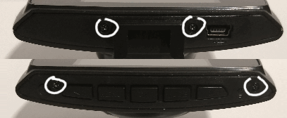
to disassemble the case to get access to the inside of the camcorder, i must remove the 'glass' that covers the screen, remove two screws from the top and from the bottom of the device. taking a prying tool (i will be using a small flathead screwdriver) and placing it into the micro usb port, being careful to not place it into the metal component on the circuit board, but the actual gap between the the top of it and the case, then i pushed down on the lever i have created. i continue to pry around the case in the new gaps that appear until the 'glass' pops off.
teardown: display
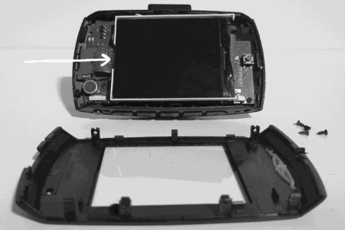
the display is a little tricky to separate, there is a sticky piece of foam holding it in place, and there is no backing to the external frame of the lcd, leaving the initial white plastic sheet of the backlight to stick to the foam. once i have unstuck the display from the circuit board, i disconnect the ribbon cable and the display comes completely free. the markings on the ribbon cable read "RXC-9225G-QM HLGD-HS122-01-22PIN" (there are 22 pins on the ribbon cable)
teardown: mobo
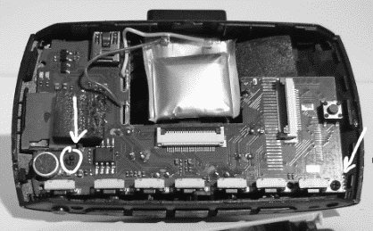
there are only two screws holding the 'mother board' in place. after those are unscrewed, i disconnect the other ribbon which goes to the camera and make sure it is separated from the sticky foam in the back, then i unstick the foam from the bottom of the case and lift the circuit board out. you could also separate the battery or the speaker cables from the foam too.
teardown: camera
(this picture will also be referenced in the next teardown section)
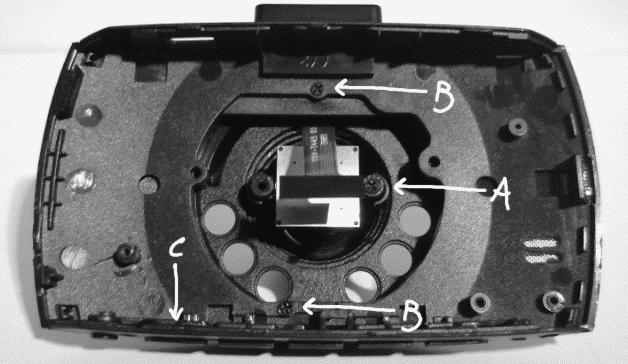
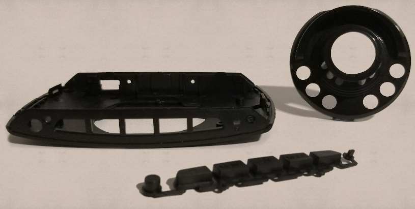
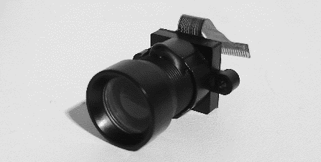
to remove the camera from the case, ill have to unscrew the screw A (which is slightly longer then all of the other screws) which will then allow me to lift the camera out of the case by the corners of the aluminum backplate. it is slightly hard to read on the image but the markings on the ribbon cable of the camera read "YXK-T445 03" with some kind of symbol underneath (it resembled an infinity sign in a box)
teardown: etc
referring back to the previous image; you can take out the plastic buttons (C) that are on the bottom of the camera, it is actually one plastic part as opposed to many separate buttons. you can also unscrew the lens unit (B) and take it off.